|
Kean Electronics |
TP-Link WR703N Teardown
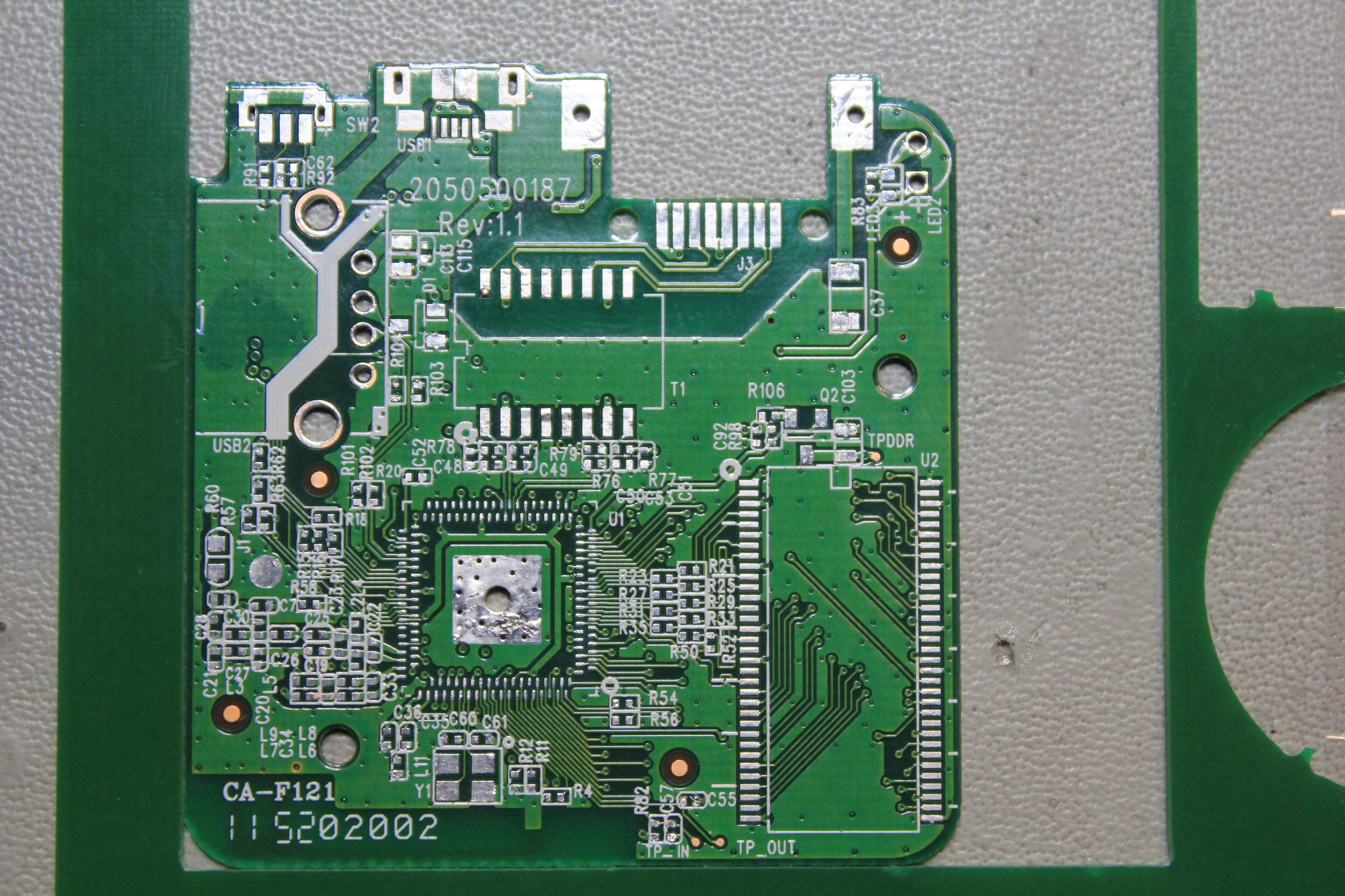
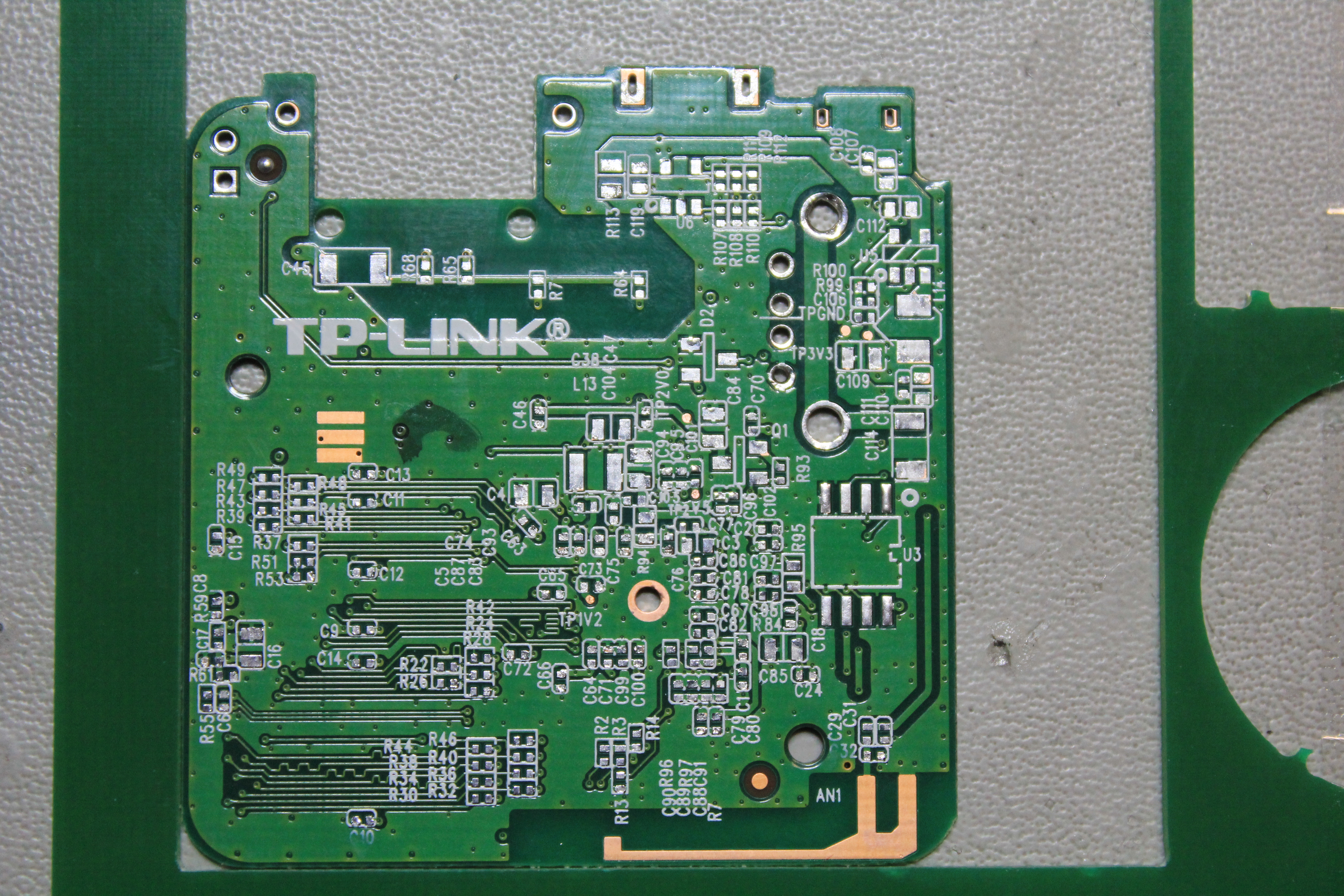
In order to better understand the TP-Link TL-WR703N design, I have painstakingly removed each component from a sacrificial unit.
This is particularly useful as the Atheros AR9331 documentation and (official) pinout is not openly available.
I did this one part at a time, and for all the SMD resistors, capacitors, and inductors I measured the values as best I could.
Finally, I cleaned up the PCB and scanned both sides to allow us to follow the PCB traces.
Later I may try shaving the PCB to allow scanning the inner layer(s).
Many thanks to Squonk on the OpenWRT forums for his encouragement and assistance with this project.
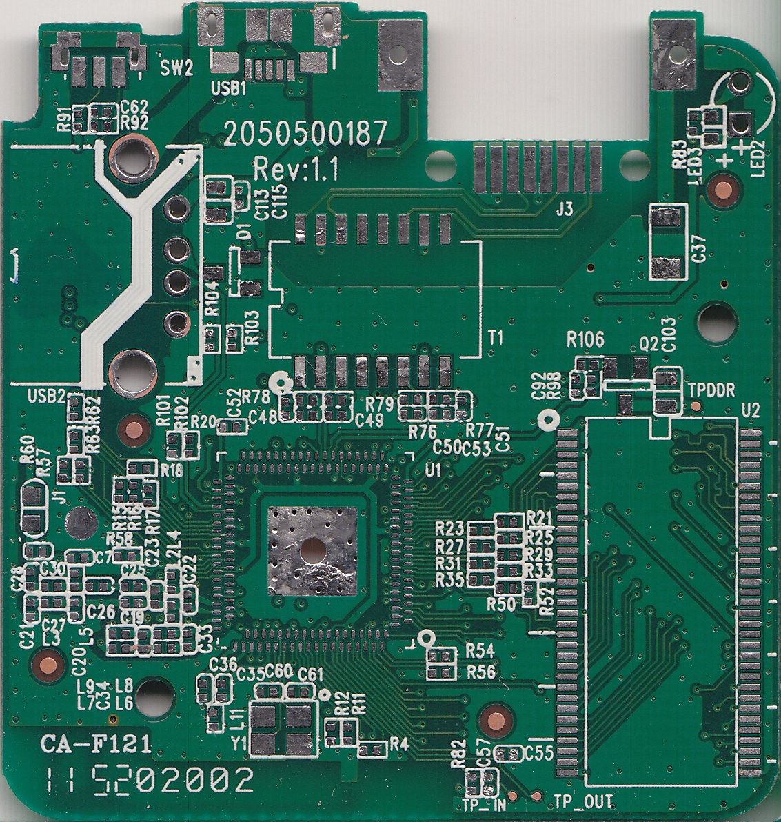
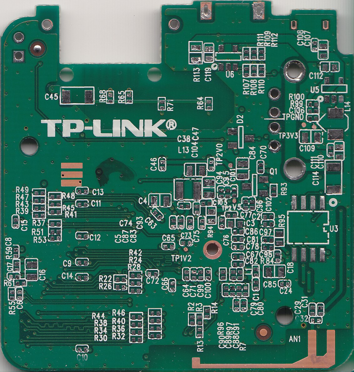
Photos
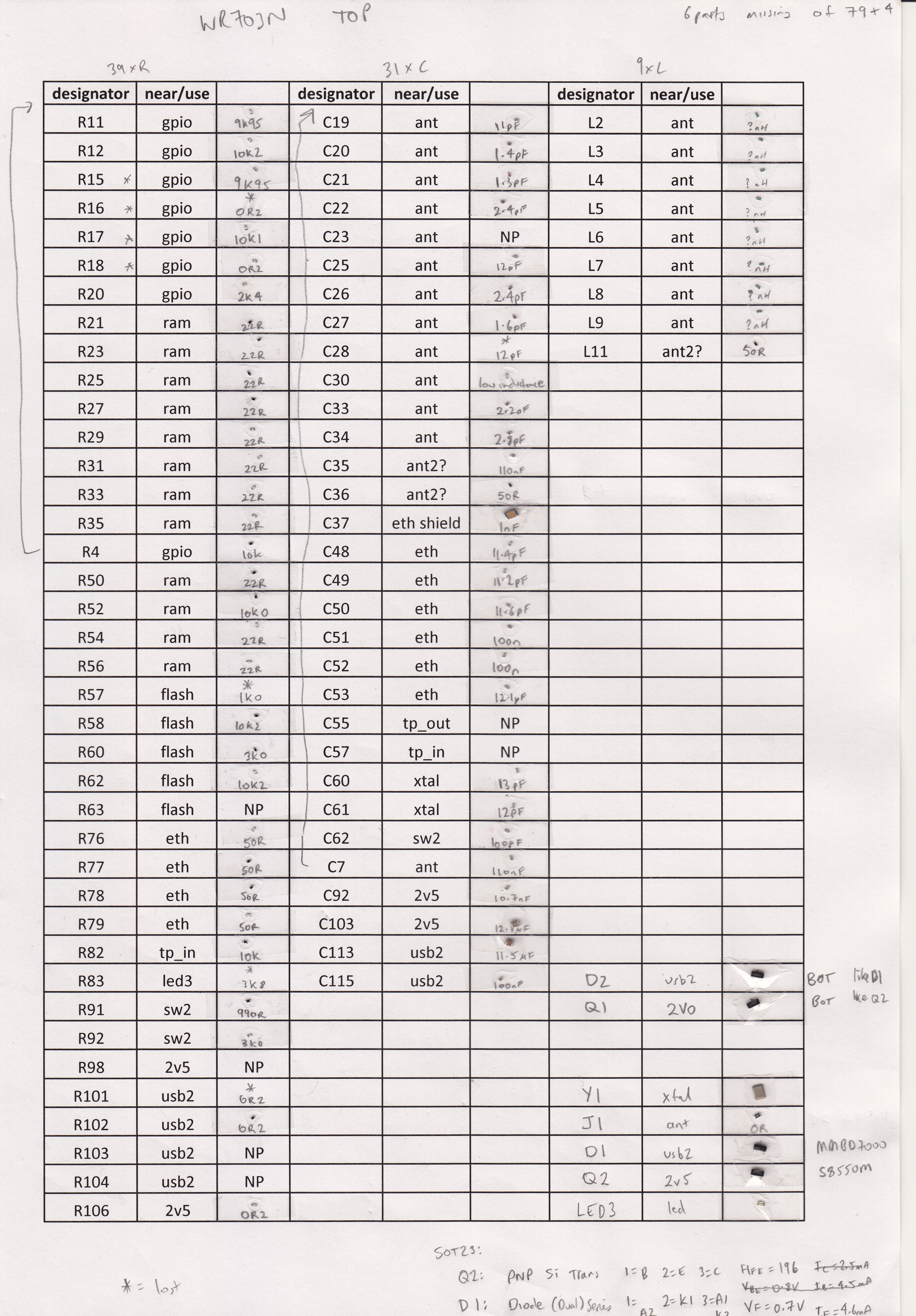
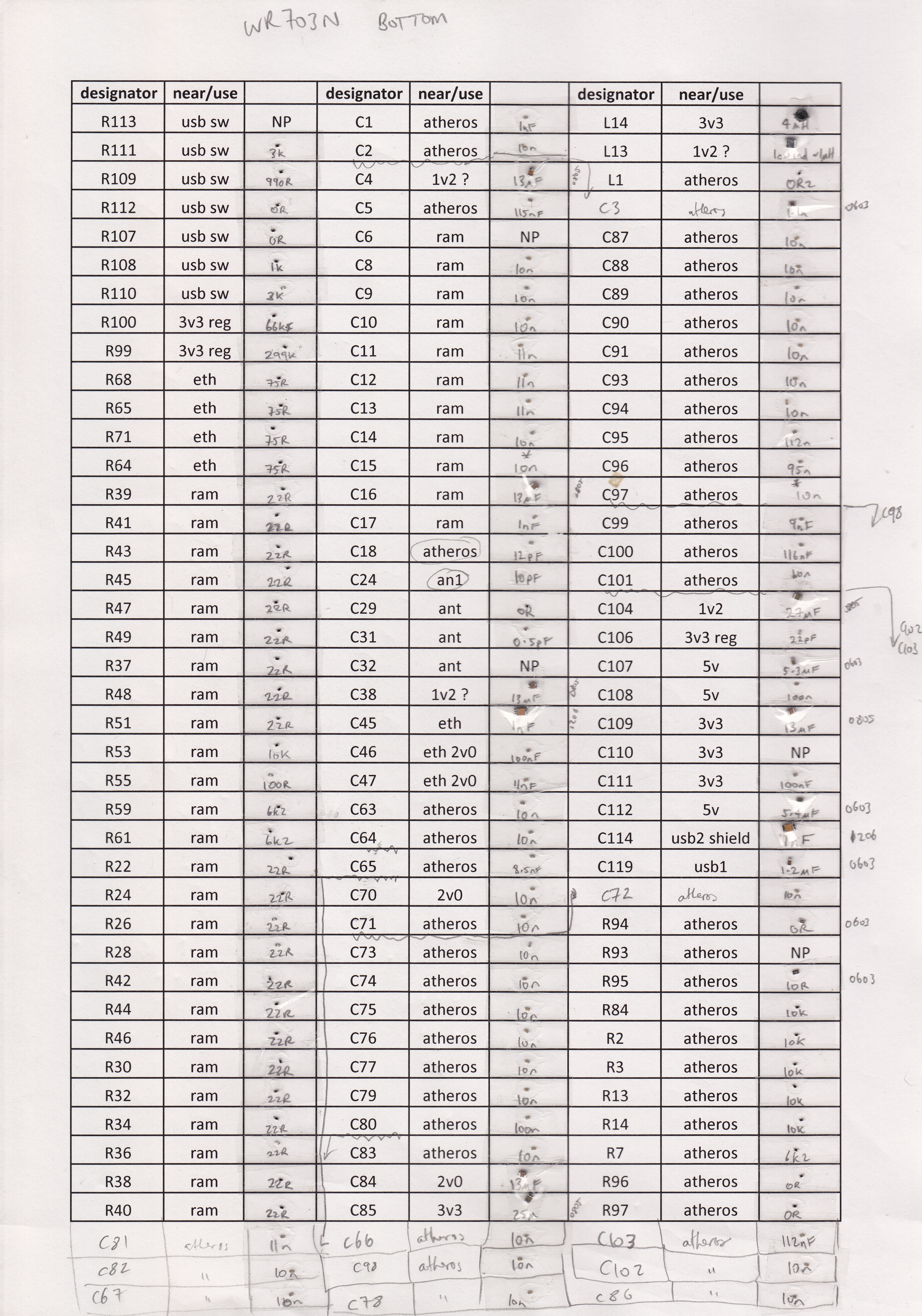
Bill of Materials
Note that due to the number of tiny components, removing and measuring them one by one took about 12 hours.
So please be aware that it is very possible that I made some mistakes here.
I also lost some of the parts in the process, and so I borrowed parts from another pcb to check where necessary.
I've rounded most values to the nearest common value.
The SMD inductors were too low in value to measure with my Atlas LCR meter.
Additional info and datasheets
License
The notes, photos, and BOM spreadsheet here are my creation and are licensed under the
Creative Commons Attribution ShareAlike license

I claim no rights to the intellectual property of TP-LINK or Atheros, or of the linked datasheets.
© 2009-2018 Kean Electronics Pty Ltd, ABN 73 627 091 196
Last updated: 2nd July 2018